![]()
![]()
![]()
![]()
![]()
![]()
![]()
![]()
![]()

FEMAP V10.2 & NX Nastran 7.1 Tutorial
Mallado 3-D con Elementos Hexaédricos
(Febrero, 2011)
Con esta página quisiera "reivindicar" la importancia de mallar en FEMAP con elementos sólidos hexaédricos "CHEXA" de 8-20 nodos en vez de mallar con elementos sólidos tetraédricos "CTETRA" de 10-nodos, siempre que sea posible, claro!. Las ventajas son múltiples:
-
Mayor precisión de los resultados del análisis por utilizar elementos de mayor calidad.
-
Menor tamaño final del modelo (a igualdad de tamaño de elemento), y por lo tanto menor tiempo de análisis.
-
En contra tenemos un mayor tiempo de preparación y adecuación de la geometría para el mallado, pero la mayor calidad de la malla y excelente precisión de los resultados del análisis hace que merezca la pena (siempre que se pueda!!) mallar con elementos hexaédricos CHEXA aunque nos suponga realizar un esfuerzo adicional.
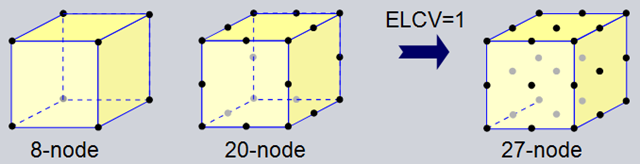
Elementos CHEXA de NX Nastran
![]() 1. Introducción al Mallado con Elementos Hexaédricos
1. Introducción al Mallado con Elementos Hexaédricos
Para mallar con elementos sólidos tipo CHEXA la geometría se
debe dividir en sólidos simples regulares
Durante el proceso de mallado con elementos hexaédricos FEMAP identifica las superficies "master" y "slave" y automáticamente ajusta las mallas en ambas superficies para que sean exactamente iguales. Este requisito de mallas "iguales" es fundamental para que el mallado hexaédrico 3D se realice con éxito. Las superficies "master" y "slave" deben producir la misma malla 2-D, no necesariamente deben tener la misma forma, pero sí el mismo número de nodos y elementos con la misma conectividad. Las superficies laterales (es decir, todo lo que no sea
|
La superficie |
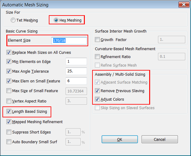
La orden "Mesh > Mesh Control > Size On Solid .." nos permite generar una malla mapeada de elementos 3-D hexaédricos por "extrusión" de una malla 2-D libre o mapeada a través del sólido. En la ventana "Automatic Mesh Sizing" debemos activar la opción "Hex Meshing" indicando que la pieza se va a mallar con elementos sólidos hexaédricos, y definimos un tamaño de elemento en el campo "Element Size = Curve Length/nº elements", el resto de opciones por defecto.
Aplicación del tamaño de malla a
la geometría para mallar con elementos Hexaédricos
Para tener mallas consistentes entre piezas FEMAP automáticamente activa la opción "Adjacent Surface Matching" en mallados con elementos Hexaédricos, mirad lo que dice el HELP:
5.1.1.5 Mesh, Mesh Control, Size On Solid...
|
|
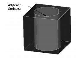
Adjacent Surface Matching
If you are specifying sizes on multiple solids at the same time, this option will set a "slaved" mesh approach on surfaces that are adjacent to each other and which are the same size. For example, in the figure, the cylinder is contained in a box with a cylindrical hole. The outer surface of the cylinder is adjacent to the similar surface of the hole through the box. To mesh these parts, you must ensure that the meshes on these two surfaces are identical. Setting one of the surfaces as a slave to the other insures a consistent mesh. This option automatically finds surfaces which are adjacent between multiple solids and slaves them to each other.
Remove Previous Slaving
This option removes all slaving from surfaces in the solids that you are sizing before proceeding with the new sizes. You will always want to leave this option on unless you have manually defined some slaved surfaces that you want to keep slaved. Turning this option off however can interfere with the proper operation of hex mesh sizing.
Adjust Colors
This option simply changes colors of surfaces during the mesh sizing process to give more information about how they were processed. It is often difficult to see all of the surfaces in a solid assembly; however, this is particularly important when you are slicing a solid in preparation for hex meshing. If you enable this option, surface colors will be adjusted as follows:
| Color | Description |
|---|---|
| Dark, Transparent Blue |
Free surfaces that were
successfully sized.
|
| Light Solid Blue |
Surfaces that were
successfully sized and which are adjacent to another
surface.
|
| Red |
Surfaces of solids that can
not be hex meshed
|
You must be displaying your model in solid, shaded Render mode for the best effect of these colors. After sizing, you can graphically see which surfaces were detected and slaved as adjacent, to make sure that all of the surfaces that you expected were found. You can also easily see which solids need to be further simplified to allow hex meshing.
../..
Tet vs. Hex Meshing
Choose the option that is appropriate to the type of meshing that you want to do. Depending on your choice however, the mesh sizing that is generated can be significantly different.
If you choose Tet meshing, the resulting sizes are similar to those created if you had simply set mesh sizes on the individual surfaces. Tet meshing does not require any additional adjustments to the mesh sizing.
Preparing for hex meshing however, requires very specific mesh sizing. Many surfaces must be mapped meshed so that the hex mesh can be generated. In addition, surfaces across multiple solids must be consistently sized and meshed so that the resulting hex mesh will be compatible. Due to this extra checking that must be done, hex mesh sizing takes much more time than tet mesh sizing.
|
Hint:
|
If you are preparing for hex meshing, you MUST select
all solids that you plan to mesh in a single command. If
you try to select them one at a time, there is no way to
guarantee that the meshes will be compatible across
different solids.
|
El color "azul-claro" indica las caras que son adjacentes y en las que la malla será coincidente y por tanto FEMAP realizará el "mergeado" automático de nodos coincidentes. En la ventana de mensajes de FEMAP podremos leer lo siguiente:
Mesh Size on Solid 3 Solid(s) Selected... Computing Mesh Sizes... Mesh Approach: Linking Surfaces 3 and 28. Mesh Approach: Linking Surfaces 12 and 29. Mesh Approach: Linking Surfaces 167 and 173. Mesh Approach: Linking Surfaces 168 and 169. |
Understanding the sweeping process
With 3D Swept Mesh, the software sweeps a mesh from the source face through the solid, to a target face. When the software generates the swept mesh, it propagates the mesh into the body, layer by layer until the entire solid body is filled with elements. The mesh on the source face, therefore, controls the mesh through the solid body.
•You can use the 2D Mapped Mesh command to first create a structured seed mesh on the source face before you use the 3D Swept Mesh command. For more information, see 2D Mapped Mesh overview.
•You can use the options in the 3D Swept Mesh dialog box to control the mesh on the source face. See Controlling the mesh on the source face in a swept mesh for more information.
In a swept mesh, the software propagates all nodes on the source surface to the target surface. For example, the software replicates any nodes created at point-based boundary condition locations on the source face on the target face. However, the software does not honor any existing entities, such as mesh points or edge densities, on target faces.
The following example shows a model with an existing free mesh of quadrilateral elements on the source face (A). The software sweeps these elements through the volume to create solid mesh of hexahedral elements (B).
**************
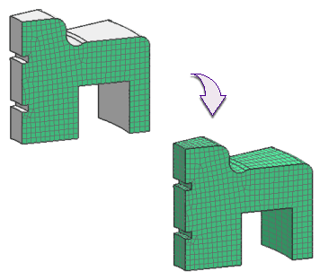
Using Split Body to subdivide a body prior to swept meshing
Before you try to generate a swept mesh on a body, you may first need to simplify the body by subdividing it into smaller bodies. You can use the Split Body command to divide a complex body into several smaller, simpler bodies. Additionally, you can use the Check for Sweepable Body option in the Split Body dialog box to interactively preview whether the current body is likely sweepable. See Split Body overview for more information.
Selecting the type of swept mesh to create
The Types menu in the 3D Swept Mesh dialog box lets you control how the software sweeps the mesh through the selected bodies.
•Select Multi Body-Infer Target to sweep a mesh from a selected source face to a target face that the software determines. You can use Multi Body-Infer Target to sweep a mesh through a single body or through multiple individual bodies. If you select source faces from multiple bodies, the software sweeps a separate mesh through each individual body.
This graphic shows the use the Multi Body-Infer Target option. Here, faces A, B, and C all selected as source faces for the mesh. Each source face belongs to a different body. The software sweeps a different mesh through each of the bodies.
•Select Until Target to sweep a mesh from a selected source face to a target face that you specify. There are two primary use cases for the Until Target option. Select the Until Target option when you want to sweep a 3D mesh from:
◦A source face in one body to a target face in another body. In this case, any intervening bodies between the source face and the target face must be contiguous.
In this graphic, we selected Until Target from the Type list and then selected face (A) as the source face and face (B) (at the bottom of the model) as the target face. When we clicked OK, the software swept the mesh from the source face, through the intermediate bodies, to the target face.
◦Multiple, connected source faces to a single target face. The following graphic shows an example of geometry in which you need to sweep a mesh from multiple source faces to a single target face. (A) shows the source faces on one side of the part, while (B) shows the target face on the opposite side of the part.
When the mesh is generated, the software sweeps the mesh of hexahedral elements from the source faces (C) to the target face (D).
Using 3D Swept Mesh to create hexahedral-tetrahedral interfaces
You can use 3D Swept Mesh to create a mapped mesh of hexahedral or tetrahedral elements to link to a free mesh of tetrahedral elements on an adjacent body. To use this capability, you must create a Glue Coincident type of Mesh Mating Condition between the bodies. Then, you use 3D Swept Mesh to create the mapped mesh. Finally, you can create the tetrahedral mesh on the adjacent body. When you solve your model, the software uses multi-point constraint equations to automatically connect the nodes on the tetrahedral and hexahedral elements.
SÍGUENOS
EN: ![]()
![]()
![]()
![]()