![]()
![]()
![]()
![]()
![]()
![]()
![]()
![]()
![]()

NX NASTRAN V5.0 ofrece las siguientes mejoras y novedades más importantes:
![]() Contenido:
Contenido:
- Dynamics
- Numerical Capabilitie
- Multi-body Dynamic Software Interfaces
- New Optimization Option
- Advanced Nonlinear
- Linear Contact Enhancements
- Strength Ratio Output for Composites
- Miscellaneous Enhancements
![]() Dynamics
Dynamics
- The constraint mode method of enforced motion, which was referred to as the relative method in NX Nastran 4.1, uses a formulation in which the response output is calculated with both the normal mode shapes, and the constraint mode shapes. A change in the default has occurred in NX Nastran 5. The absolute displacement formulation is used as the default SPC/SPCD method.
- A new mode acceleration formulation with improved performance has been added in this release to supplement the current algorithm. The improved performance makes mode acceleration a more attractive option when increased accuracy is desired.
- Up until the release of NX Nastran version 4.0, only auto spectrum PSD functions of response could be output for random results. It was required to use DMAP alters to obtain cross spectrum results. In NX Nastran 4.1, the option to output cross-power spectral density functions became available. Now with NX Nastran 5.0, it is possible to also request cross-correlation functions.
- The Dynamic Design Analysis Method (DDAM) is a list of procedures to determine modal shock response. To complete DDAM analysis procedures in previous releases of NX Nastran, the use of dmap alter files were required. Now in NX Nastran 5,these DDAM procedures have been streamlined and automated, thus eliminating the alter requirement.
- The element strain (ESE), kinetic (EKE), and damping (EDE) case control commands have been improved to allow the output of element energy information in SORT2 complex format. This format is suitable for plotting complex function data from frequency domain dynamic solutions. In previous releases, you could only output the real magnitude of element energy, thus no phase information was written. In addition, only SORT1 format could be output, which is not convenient for function plotting.
- Rotor dynamics can now be used in a modal frequency response solution, SOL 111, to calculate the dynamic response of a rotating system. This new response calculation adds to the existing rotor dynamics capability, direct complex mode solution, SOL 110, whose output is used to create Campbell diagrams.
- When the modal method is used for dynamic response calculations, understanding which modes contribute to the response helps understand the dynamic behavior of the simulated system, and can provide insight as to how to improve the dynamic performance. In this release a new capability has been introduced to compute the modal contributions in modal frequency response.
- A structural damping matrix can now be included with a model in NX Nastran 5 using the new K42GG case control command. This ability adds to the other direct matrix capabilities of stiffness, mass, and damping matrices using DMIG bulk entries.
![]() Numerical
Capabilities
Numerical
Capabilities
- A new sparse data recovery option is available for the modal frequency response analysis (SOL 111), modal transient response analysis (SOL 112), and optimization (SOL 200) as the new default. For SOL 111 and 112, this feature reduces the cost of matrix-multiplications inside DDRMM modules when large amount of data are requested to recover in the modal analysis. Similarly, SOL 200 utilize the partitioning of eigenvector matrix in order to reduce the cost of matrix-matrix multiplies.
- The
parallel processing method Distributed Memory Parallel (DMP) has been
enhanced in NX Nastran 5 with the following additions:
- The normal mode calculation portion of an optimization solution (SOL 200) can now use DMP.
- A new linear statics (SOL 101) DMP option, Load Domain Static Analysis (LDSTAT), now exists to decrease the solution times when large numbers of load cases exist.
- This NX Nastran release includes support for a new sparse Cholesky decomposition. All users of Cholesky decomposition (including the Givens and Householder eigensolver methods) will utilize sparse decomposition by default, which can be considerably faster than the non-sparse Cholesky decomposition method used in earlier NX Nastran versions.
- NX Nastran Version 5.0 introduces the new REDMULT performance option for use when solving vibration problems with the Lanczos method. This option reduces the cost of matrix-vector multiplies inside the READ module when the mass matrix involved is relatively dense, which can occur when a large number of MFLUID is present in the model.
![]() Multi-body
Dynamic Software Interfaces
Multi-body
Dynamic Software Interfaces
- This release includes interoperability between NX Nastran and the FunctionBay RFI (RecurDyn Flex Input) file product. You can now create a RecurDyn Flex Input file (RFI) directly from NX Nastran. The RFI contains the reduced order matrices from the results of a NX Nastran non-restart SOL 103 analysis. The RFI can be imported into RecurDyn and used to represent a flexible component in a multi-body dynamics analysis. This direct RFI export capability streamlines the process of creating flexible components from FE models, making it possible to obtain more accurate results from multi-body simulations.
- NX Nastran 5 enhances the ADAMS MNF file creation process with a new results recovery capability. The results from an ADAMS multi-body dynamics analysis, along with an optional component modal definitions file (OUTPUT2 format), are used in a consecutive NX Nastran SOL 103 results recovery solution.
- The set-up of a flex body modal solution in NX Nastran for export to ADAMS MNF or Recurdyn RFI files requires special considerations for the modal solution. This is because flex bodies will be attached to other components in the multi-body dynamic (MBD) simulation and local flexibility effects at the connection locations are thus important. A modal solution method called Component Mode Reduction of Residual Structure (CMR of RS) is recommended for flex body solutions because it includes both global and local effects. The details of this method are presented in the multi-body dynamic chapter.
![]() New
Optimization Option
New
Optimization Option
- NX Nastran 5 introduces a new optimizer option, UGS-ADS, which is based on public domain ADS code.
![]() Advanced
Nonlinear
Advanced
Nonlinear
- The CTDISP option has been created on the NXSTRAT bulk entry to prevent contact conditions from updating.
- A new option on the NXSTRAT bulk entry, CTDAMP, has been created to stabilize the portions of the model experiencing rigid body motion, thus helping the solution to continue and converge.
- A new option when INIPENE=3 is available which will include both penetration and now gaps. This option is particularly beneficial when contact conditions are defined on the faces of concentric cylinders.
- In NX Nastran 4.1, a new contact segment option became available for SOL 601 which improved contact results. This improvement matches the order of the contact segments with the order of the elements. The restrictions which existed in NX Nastran 4.1 when CSTYPE=1 have been eliminated in NX Nastran 5.
- The contact algorithm has been improved in NX Nastran 5 to be more robust for contact with friction.
- The option to “glue” element faces together during a 601 solution is available in NX Nastran 5. The glue option connects predefined surfaces together and prevents relative motion in all directions. Predefined regions of element free faces are used to detect where the glue elements are created.
- An option to define element birth and death times for a specific set of elements is available in NX Nastran 5.
- NX Nastran 5 offers an automated method to simplify the multisolution process of bolt preloads with SOL 601.
- A new shell thickness result output option is available when using advanced nonlinear to solve large strain problems.
- A new 3D-iterative solution option is now available in NX Nastran 5 for SOL 601 to efficiently solve large models containing mainly higher order 3-D solid elements (e.g., 10-node CTETRA, 20-node CHEXA, etc.).
![]() Linear
Contact Enhancements
Linear
Contact Enhancements
- Two new contact solution parameters, INTORD and REFINE, are now available in NX Nastran 5 on the BCTPARM bulk entry to improve the accuracy of the contact solution.
- Now in NX Nastran 5, a contact definition can be included in a normal mode solution (SOL 103), and in an optional modal dynamic response calculation (SOLs 111 and 112).
- In NX Nastran 5, the use of superelements is now permitted in solution sequences which support contact (SOLs 101, 103, 111 and 112). The only requirement is that the contact definition must occur in the residual structure.
- Now in NX Nastran 5, the linear contact solution can include the shell element ZOFFS when evaluating the contact surfaces.
![]() Strength
Ratio Output for Composites
Strength
Ratio Output for Composites
- Strength ratio is now output together with the failure index when using the PCOMP bulk entry. Strength ratio is a more direct indicator of failure than failure index since it demonstrates the percentage of applied load to the failure criteria.
![]() Thermal
Expansion of Rigid Elements
Thermal
Expansion of Rigid Elements
- The option to include rigid elements in thermal expansion calculations is available in NX Nastran 5. The new case control command, RIGID, should be assigned to “LAGRAN” to use the new method. In addition, the coefficient of thermal expansion (ALPHA) has been added as an additional entry on the rigid elements: RBAR, RBE1, RBE2, RROD, RTRPPLT. This capability is supported in solutions 101 through 112.
- When the RIGID case control command is set to the default of “LINEAR”, the original linear elimination method is used. This method treats rigid elements as an MPC equation without thermal loading effects. The new RIGID case control command is duplicated below for convenience.
![]() Bolt
Preload Analysis
Bolt
Preload Analysis
When components of an assembly are bolted together, a specified torque translates into an axial bolt preload. Bolts should be properly preloaded in this way before service conditions are applied to the assembly. When analyzing preloaded bolts, you may be interested in obtaining the stresses due to the preload condition alone, or due to a combination of the bolt preload and service load. You can manually determine the preloaded bolt condition by using equivalent thermal loads, although using this method is approximate and typically requires many solution iterations when multiple bolts exist.
NX Nastran 5 offers an automated method to simplify this multisolution process. A bolt analysis can be selected by including the new case control command BOLTLD=n, where "n" selects the new BOLTFOR bulk data entry containing the bolt preload value. The bolts should be modeled as beam elements, and included in the new BOLT bulk entry. One BOLT entry is required to define each physical bolt. The service loads can also be included and are selected using the LOAD case control command. Superelements are permitted with preloaded bolts but the elements which define the bolts must be in the residual structure.
NX Nastran uses the following two solution process to automate the preloading of bolts:
- The beam elements which represent the bolts are reduced in stiffness by the value of the parameter BOLTFACT which makes their stiffness insignificant.
- The bolt preloads are applied at the ends of the bolts in the axial direction.
- A linear statics solution runs to get the relative displacements, U2 and U1, for each pair of grids.
- The
bolt strains are calculated as:
- Bolt
Strain = – (U2-U1)/L – P/AE
where U1 and U2 are the deflections at the ends of the bolts, P is the preload, and A is the area of the bolt. - In the final solution step, the bolts are treated as they were modeled (beam elements), then the calculated bolt strains are applied plus any service loads (if defined).
- Bolt
Strain = – (U2-U1)/L – P/AE
![]() Element
Iterative Solver Support of Surface Glue
Element
Iterative Solver Support of Surface Glue
In NX Nastran 4.1, a new option to “glue” element faces together during a solution became available. Glue definitions, which are supported in all solution sequences except for SOL 701, create stiff springs to connect the pre-defined surfaces. Glue elements connect components together in such a way as to prevent all relative motion. Glue definitions in a SOL 153 heat transfer analysis are treated as near infinite conductivity connections.
The surface-to-surface glue capability was supported by the global iterative solver in NX Nastran 4.1, but not by the element iterative solver. Now in NX Nastran 5, the surface-to-surface glue definitions can be included when using the element iterative solver. To utilize the element based iterative solver, add the keyword ELEMITER=YES
![]() Glue
Accuracy Improvement
Glue
Accuracy Improvement
NX Nastran uses pre-defined source and target regions of element free faces to detect glue conditions in the model. More specifically, the solver uses the element faces from a source region to project normals, then checks if these normals intersect with other element faces on a target region.
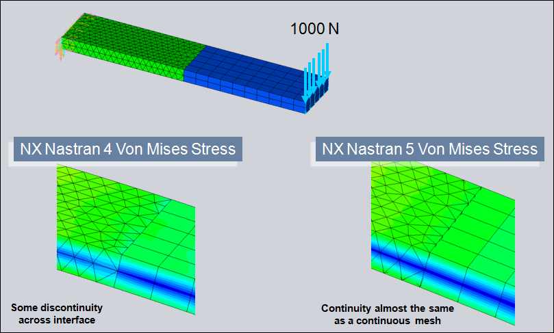
Mejoras en Glue-Contact de
NX NASTRAN V5.0
A glue element is created if:
- NX Nastran finds an intersection between element faces, and
- The distance between the two faces is equal to or less than a distance that you specify.
The number of glue elements created and their distribution determine the accuracy of the glued interface
Two new glue solution parameters, INTORD and REFINE, are now available in NX Nastran 5 on the BGPARM bulk entry to improve the accuracy of the glue solution. The updated BGPARM bulk entry is repeated below for convenience.
Previously, the number of locations where normals were projected (glue points) from the source region was dependent on the element type. For example, the linear triangle face would always project a single normal, while the parabolic quad would project 4 normals.
Now in NX Nastran 5, the number of glue points used is dependent on the value assigned to the new INTORD parameter, and on the element face type. By default, INTORD=2 and the number of glue points increases as compared to the previous release. When INTORD=1, the number of glue points is the same as the previous release. The following table summarizes how the INTORD value adjusts the number of glue points for a particular element face:
|
Number of Glue Points Used in Glue Element Evaluation |
|||
|
Face Type |
INTORD=1 |
INTORD=2 (default) |
INTORD=3 |
|
Linear Triangle |
1 |
3 |
7 |
|
Parabolic Triangle |
3 |
7 |
12 |
|
Linear Quad |
1 |
4 |
9 |
|
Parabolic Quad |
4 |
9 |
16 |
The new REFINE parameter increases the number of glue points by refining the mesh on the source region. Part of the refinement process is to project element edges and grids from the associated target region back to the source region. The resulting refinement on the source region is then more consistent with the target side, which then gives a better distribution of glue elements. The refined grids and elements are only used during the solution. The glue results are transferred back to the original mesh for post processing results.
By default, REFINE=1 and mesh refinement occurs. REFINE=0 turns off the refinement capability.
![]() Shell
Element Z-offset with Surface Glue
Shell
Element Z-offset with Surface Glue
Shell elements such as the CQUAD4 can be offset relative to the mean plane of their connected grid points using the ZOFFS option. In NX Nastran 5, the surface glue solution can include the shell element ZOFFS when evaluating the glue surfaces. The value assigned to the new ZOFFSET option on the BGPARM bulk entry determines if the glue solution recognizes the ZOFFS value. By default, ZOFFSET=0 and the ZOFFS value is used when evaluating the glue surfaces. When ZOFFSET=1, the ZOFFS value is not used when evaluating the glue surfaces.
SÍGUENOS
EN: ![]()
![]()
![]()
![]()